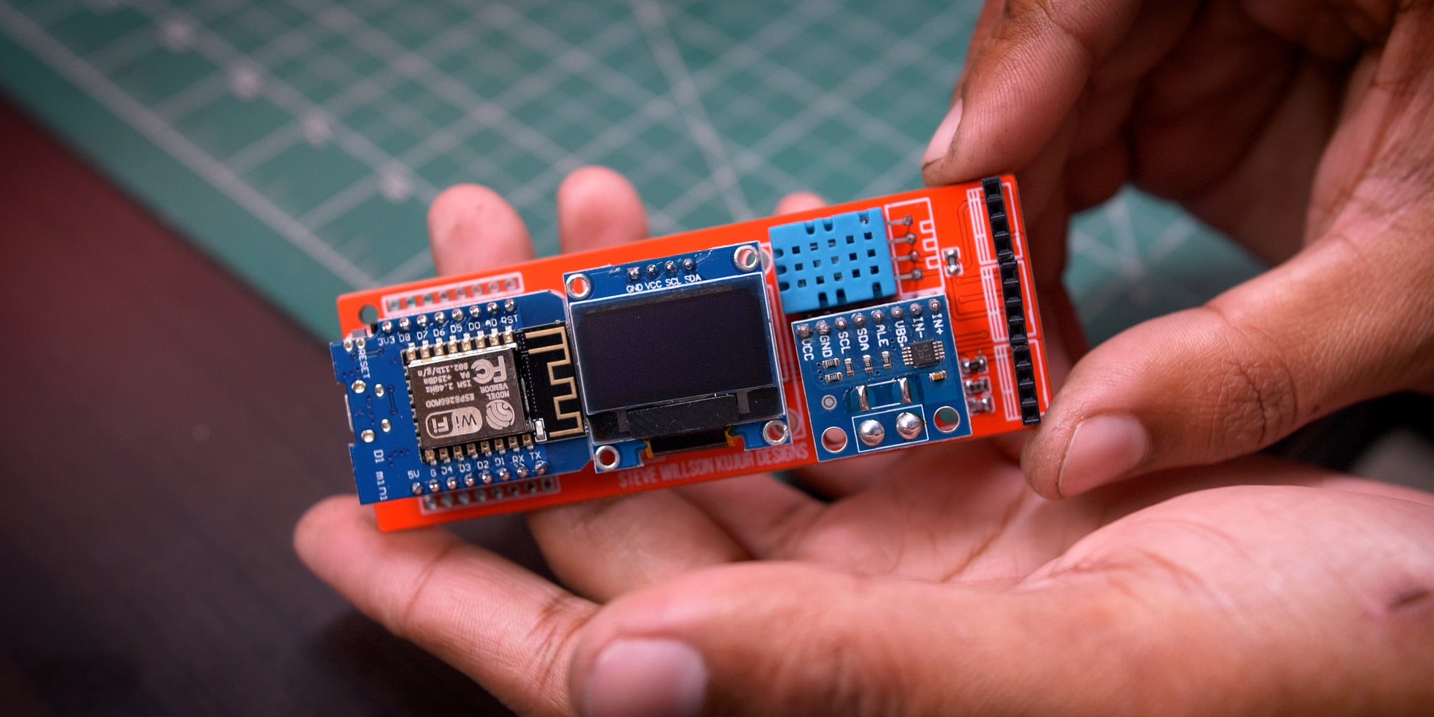
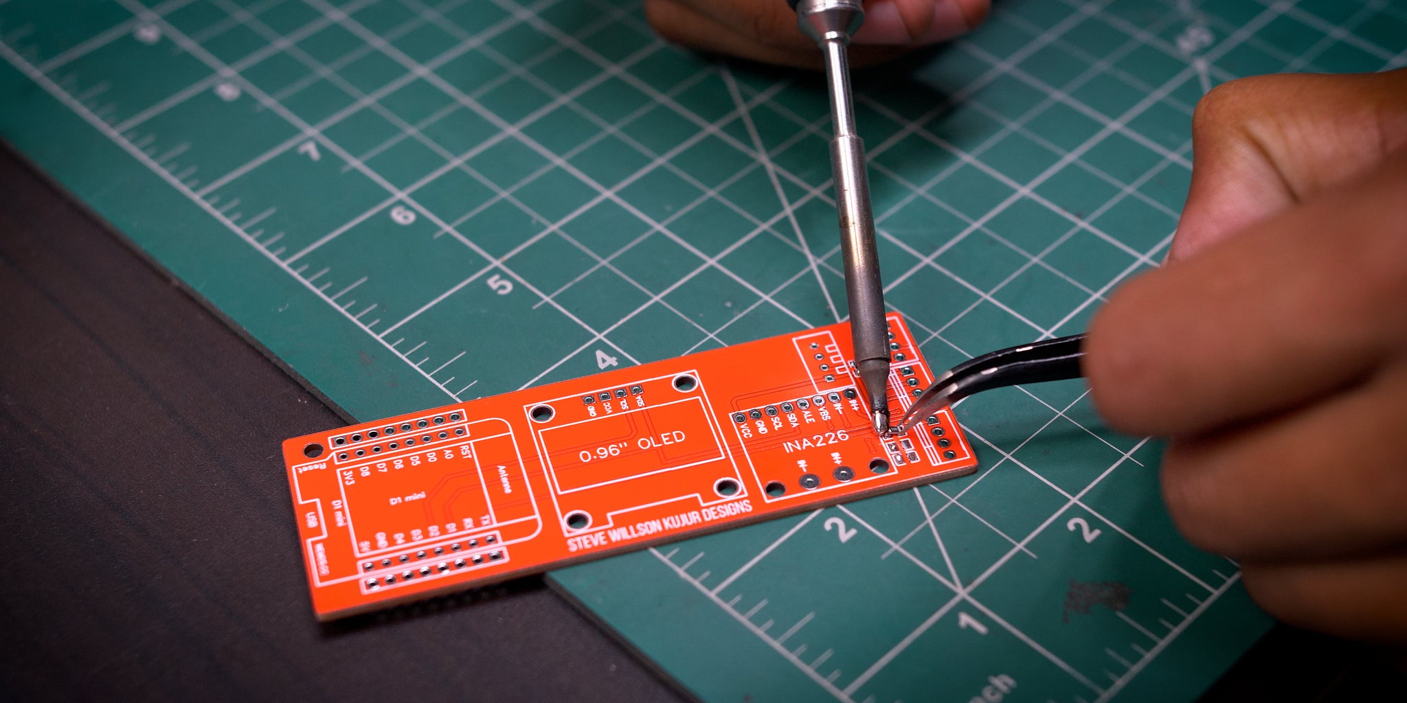
100VDC 100A 16 Steps with Pictures Circuit Diagram In this tutorial, we will guide you step-by-step on how to build your own 3-phase WiFi electricity meter using commonly available components such as ESP8266, Smart power meters allow and facilitate two-way (networked) communication between the meter and the central electrical system. That's what makes it "smart".
Stream Full Episodes of How It's Made:https://www.discoveryplus.com/show/how-its-madeSubscribe to Science Channel:http://bit.ly/SubscribeScienceLike us on Fa Learn how to build a smart IoT-based energy monitoring device to see real-time energy usage right on your smartphone.

Smart Electricity Power Meters Circuit Diagram
Overview In this project, we will learn how to make our own IoT Based Electricity Energy Meter using ESP32 & monitor data on the Blynk Application. How to make a smart energy meter to monitor and reduce your home's electricity consumption - an easy DIY guide to build your own IoT-enabled power meter.
Explore our guide to smart meters, smart metering & AMI! Learn how they work, their key components & how they make energy management smarter and greener. This Project design, IoT Smart Energy BilIing Meter, is the design and construction of an energy meter that is being used to monitor the power consumption of consumers. An IoT dashboard will also be created that will show the amount of power that has been consumed, and a bill will be generated based on the amount of power that has been consumed. The project design uses WiFi connectivity to
